ESP32 Project 5 - Output-Display & PWM
Hallo semuanya, jumpa lagii, pada project ke lima ini kita akan melakukan eksperimen menggunakan modul display dan mengenerate sinyal PWM.
Sumber dari project ini berasal dari https://randomnerdtutorials.com/esp32-ssd1306-oled-display-arduino-ide/ untuk eksperimen modul display, dan https://randomnerdtutorials.com/esp32-pwm-arduino-ide/ untuk generate sinyal PWM.
Display
Mengenal Display OLED 0.96”
OLED Display 0.96 inch 128×64 ini menggunakan driver SSD1306, salah satu controller OLED paling populer dan stabil untuk komunikasi I2C. Menggunakan teknologi OLED (Organic Light Emitting Diode) sehingga tidak membutuhkan backlight, menghasilkan tampilan kontras tinggi, sudut pandang lebar, dan tetap jelas meskipun di ruangan gelap.
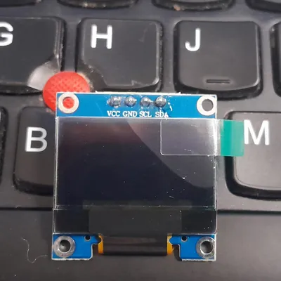
Modul Display Tersebut menggunakan protokol komunikasi I2C, sehingga kita akan menggunakan pin SDA (GPIO21) dan SCL (GPIO22) pada board ESP32 yang saya miliki.
Berikut adalah spesifikasi dari modul display tersebut:
- Interface: I2C (3.3V / 5V logic level)
- Resolution: 128 x 64
- Ukuran layar: 0.96 inch
- Angle of view: >160 degree
- Display color: White
- Power supply: DC3.3V~5V
- Operating temperature: -20’C~70’C
Berikut adalah spesifikasi dari sensor tersebut:
- Menampilkan, karekter display
- Output Display
Untuk harganya sendiri, saya membeli dengan harga yang sangat murah yakni Rp28.900,-.
Install library SSD1306 OLED
Ada beberapa library yang mampu menampilkan display OLED, namun pada kesempata ini kita gunakan dua librari dari Adafruit yaitu Adafruit_SSD1306 library and Adafruit_GFX library.
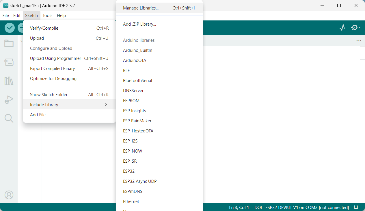
Cara menginstall pada Arduino IDE adalah klik Sketch > Include Library > Manage Libraries.
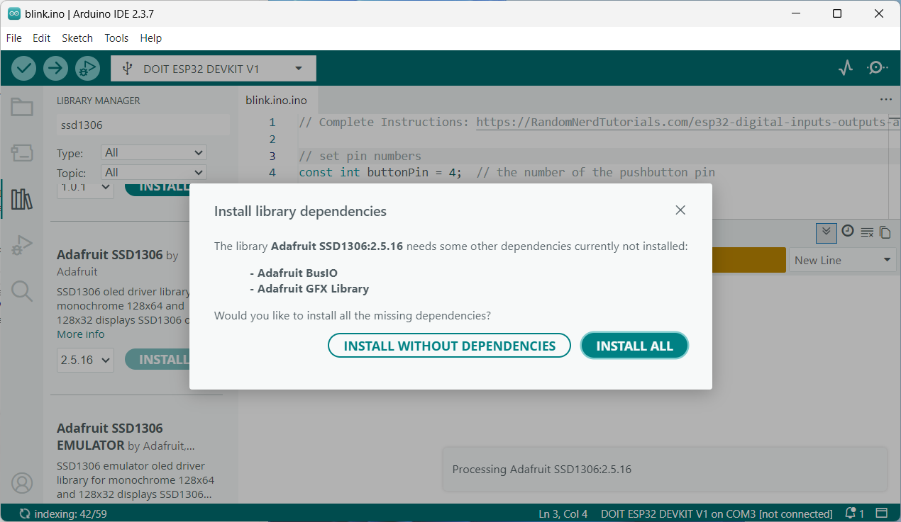
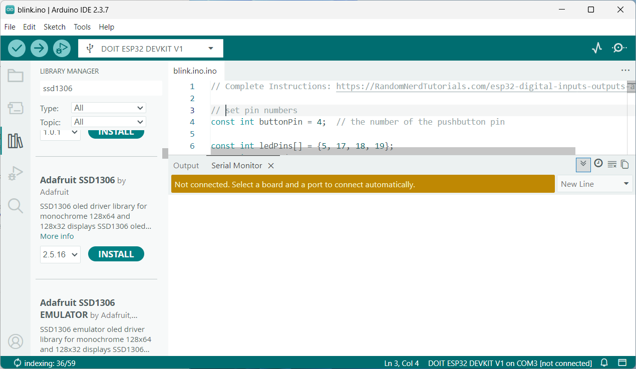
Kemudian muncul menu pencarian disamping kiri, silahkan cari “ssd1306” pilih yang Adafruit BMP085 Library by Adafruit ya, kemudian klik INSTALL, jika muncul pesan Install library depedencies?, klik INSTALL ALL. Untuk librari Adafruit GFX nya sudah termasuk depedencies nya sehingga sekalian install. Jika sudah berhasil terinstall, restart Aruino IDE.
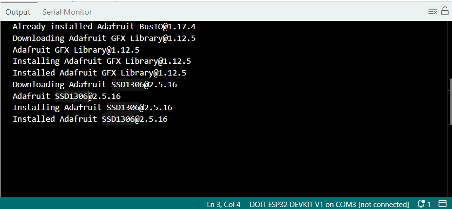
Gambar rangkaian instalasi library SSD1306 OLED
Rangkaian
Berikut rangkaian yang digunakan:
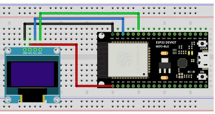
Jadi pada gambar tersebut, terdapat 4 pin sensor BMP180 yaitu GND, SCL, SDA, dan 3v3. Dimana masing-masing pin tersebut terhubung ke:
- GND terhubung ke GND
- SCL terhubung ke GPIO22
- SDA terhubung ke GPIO21
- 3v3 terhubung ke 3v3
Berikut hasil rangkaian yang telah dibuat:
gambar hasil rangkaian
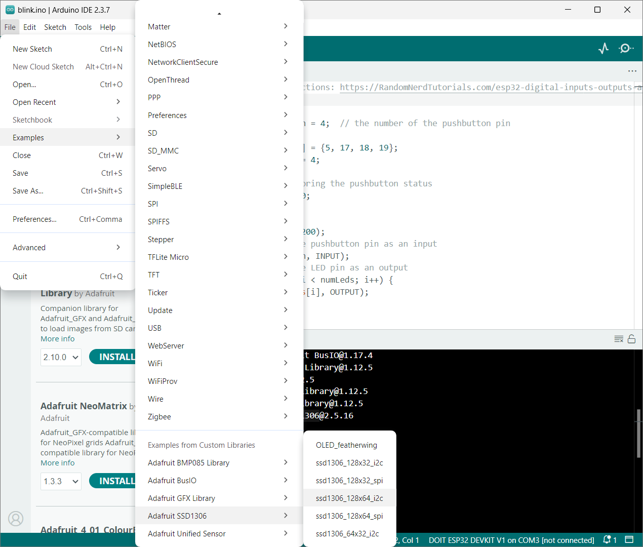
Uji Coba Example Code
Setelah rangkaian berhasil terpasang dengan baik dan library telah diinstall, kita akan gunakan contoh code dari librarinya, klik File > Examples > Adafruit SSD1306 kemudian pilih ssd1306_128x64_i2c. Angka x64 disini bukan menunjukkan sistem operasi 64bit ya, melainkan resolusi dari display itu sendiri, jadi silahkan liat di spesifikasi displaynya, yakni 128x64.
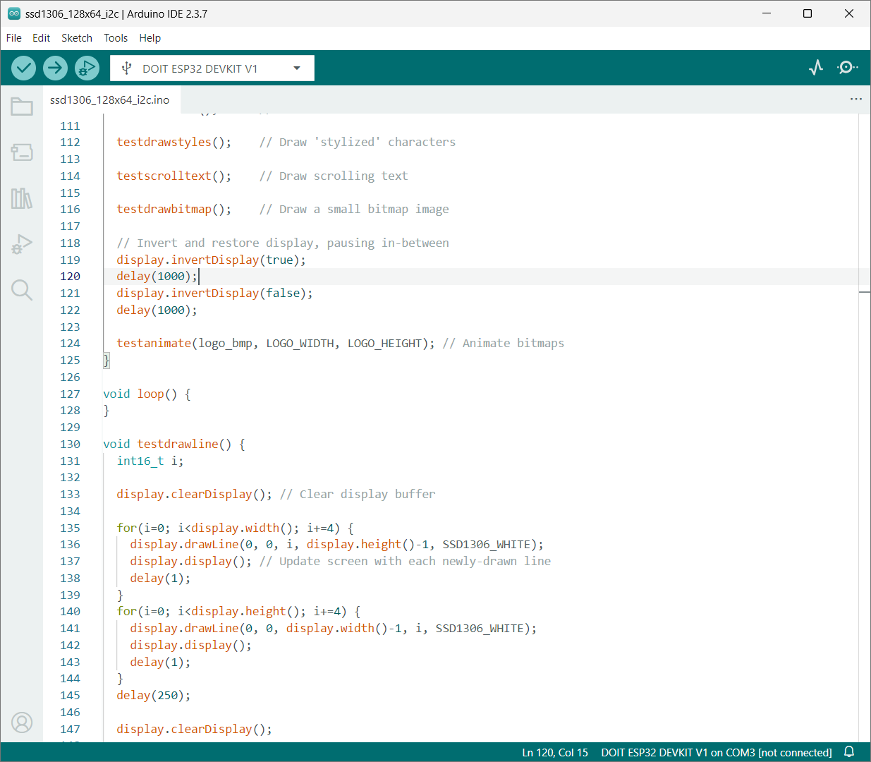
Ini adalah code yang digunakan untuk resolusi 128x64
/**************************************************************************
This is an example for our Monochrome OLEDs based on SSD1306 drivers

Pick one up today in the adafruit shop!
------> http://www.adafruit.com/category/63_98

This example is for a 128x64 pixel display using I2C to communicate
3 pins are required to interface (two I2C and one reset).

Adafruit invests time and resources providing this open
source code, please support Adafruit and open-source
hardware by purchasing products from Adafruit!

Written by Limor Fried/Ladyada for Adafruit Industries,
with contributions from the open source community.
BSD license, check license.txt for more information
All text above, and the splash screen below must be
included in any redistribution.
**************************************************************************/

#include <SPI.h>
#include <Wire.h>
#include <Adafruit_GFX.h>
#include <Adafruit_SSD1306.h>

#define SCREEN_WIDTH 128 // OLED display width, in pixels
#define SCREEN_HEIGHT 64 // OLED display height, in pixels

// Declaration for an SSD1306 display connected to I2C (SDA, SCL pins)
// The pins for I2C are defined by the Wire-library.
// On an arduino UNO:       A4(SDA), A5(SCL)
// On an arduino MEGA 2560: 20(SDA), 21(SCL)
// On an arduino LEONARDO:   2(SDA),  3(SCL), ...
#define OLED_RESET     -1 // Reset pin # (or -1 if sharing Arduino reset pin)
#define SCREEN_ADDRESS 0x3D ///< See datasheet for Address; 0x3D for 128x64, 0x3C for 128x32
Adafruit_SSD1306 display(SCREEN_WIDTH, SCREEN_HEIGHT, &Wire, OLED_RESET);

#define NUMFLAKES     10 // Number of snowflakes in the animation example

#define LOGO_HEIGHT   16
#define LOGO_WIDTH    16
static const unsigned char PROGMEM logo_bmp[] =
{ 0b00000000, 0b11000000,
0b00000001, 0b11000000,
0b00000001, 0b11000000,
0b00000011, 0b11100000,
0b11110011, 0b11100000,
0b11111110, 0b11111000,
0b01111110, 0b11111111,
0b00110011, 0b10011111,
0b00011111, 0b11111100,
0b00001101, 0b01110000,
0b00011011, 0b10100000,
0b00111111, 0b11100000,
0b00111111, 0b11110000,
0b01111100, 0b11110000,
0b01110000, 0b01110000,
0b00000000, 0b00110000 };

void setup() {
Serial.begin(9600);

// Wait for display
delay(500);

// SSD1306_SWITCHCAPVCC = generate display voltage from 3.3V internally
if(!display.begin(SSD1306_SWITCHCAPVCC, SCREEN_ADDRESS)) {
  Serial.println(F("SSD1306 allocation failed"));
  for(;;); // Don't proceed, loop forever
}

// Show initial display buffer contents on the screen --
// the library initializes this with an Adafruit splash screen.
display.display();
delay(2000); // Pause for 2 seconds

// Clear the buffer
display.clearDisplay();

// Draw a single pixel in white
display.drawPixel(10, 10, SSD1306_WHITE);

// Show the display buffer on the screen. You MUST call display() after
// drawing commands to make them visible on screen!
display.display();
delay(2000);
// display.display() is NOT necessary after every single drawing command,
// unless that's what you want...rather, you can batch up a bunch of
// drawing operations and then update the screen all at once by calling
// display.display(). These examples demonstrate both approaches...

testdrawline();      // Draw many lines

testdrawrect();      // Draw rectangles (outlines)

testfillrect();      // Draw rectangles (filled)

testdrawcircle();    // Draw circles (outlines)

testfillcircle();    // Draw circles (filled)

testdrawroundrect(); // Draw rounded rectangles (outlines)

testfillroundrect(); // Draw rounded rectangles (filled)

testdrawtriangle();  // Draw triangles (outlines)

testfilltriangle();  // Draw triangles (filled)

testdrawchar();      // Draw characters of the default font

testdrawstyles();    // Draw 'stylized' characters

testscrolltext();    // Draw scrolling text

testdrawbitmap();    // Draw a small bitmap image

// Invert and restore display, pausing in-between
display.invertDisplay(true);
delay(1000);
display.invertDisplay(false);
delay(1000);

testanimate(logo_bmp, LOGO_WIDTH, LOGO_HEIGHT); // Animate bitmaps
}

void loop() {
}

void testdrawline() {
int16_t i;

display.clearDisplay(); // Clear display buffer

for(i=0; i<display.width(); i+=4) {
  display.drawLine(0, 0, i, display.height()-1, SSD1306_WHITE);
  display.display(); // Update screen with each newly-drawn line
  delay(1);
}
for(i=0; i<display.height(); i+=4) {
  display.drawLine(0, 0, display.width()-1, i, SSD1306_WHITE);
  display.display();
  delay(1);
}
delay(250);

display.clearDisplay();

for(i=0; i<display.width(); i+=4) {
  display.drawLine(0, display.height()-1, i, 0, SSD1306_WHITE);
  display.display();
  delay(1);
}
for(i=display.height()-1; i>=0; i-=4) {
  display.drawLine(0, display.height()-1, display.width()-1, i, SSD1306_WHITE);
  display.display();
  delay(1);
}
delay(250);

display.clearDisplay();

for(i=display.width()-1; i>=0; i-=4) {
  display.drawLine(display.width()-1, display.height()-1, i, 0, SSD1306_WHITE);
  display.display();
  delay(1);
}
for(i=display.height()-1; i>=0; i-=4) {
  display.drawLine(display.width()-1, display.height()-1, 0, i, SSD1306_WHITE);
  display.display();
  delay(1);
}
delay(250);

display.clearDisplay();

for(i=0; i<display.height(); i+=4) {
  display.drawLine(display.width()-1, 0, 0, i, SSD1306_WHITE);
  display.display();
  delay(1);
}
for(i=0; i<display.width(); i+=4) {
  display.drawLine(display.width()-1, 0, i, display.height()-1, SSD1306_WHITE);
  display.display();
  delay(1);
}

delay(2000); // Pause for 2 seconds
}

void testdrawrect(void) {
display.clearDisplay();

for(int16_t i=0; i<display.height()/2; i+=2) {
  display.drawRect(i, i, display.width()-2*i, display.height()-2*i, SSD1306_WHITE);
  display.display(); // Update screen with each newly-drawn rectangle
  delay(1);
}

delay(2000);
}

void testfillrect(void) {
display.clearDisplay();

for(int16_t i=0; i<display.height()/2; i+=3) {
  // The INVERSE color is used so rectangles alternate white/black
  display.fillRect(i, i, display.width()-i*2, display.height()-i*2, SSD1306_INVERSE);
  display.display(); // Update screen with each newly-drawn rectangle
  delay(1);
}

delay(2000);
}

void testdrawcircle(void) {
display.clearDisplay();

for(int16_t i=0; i<max(display.width(),display.height())/2; i+=2) {
  display.drawCircle(display.width()/2, display.height()/2, i, SSD1306_WHITE);
  display.display();
  delay(1);
}

delay(2000);
}

void testfillcircle(void) {
display.clearDisplay();

for(int16_t i=max(display.width(),display.height())/2; i>0; i-=3) {
  // The INVERSE color is used so circles alternate white/black
  display.fillCircle(display.width() / 2, display.height() / 2, i, SSD1306_INVERSE);
  display.display(); // Update screen with each newly-drawn circle
  delay(1);
}

delay(2000);
}

void testdrawroundrect(void) {
display.clearDisplay();

for(int16_t i=0; i<display.height()/2-2; i+=2) {
  display.drawRoundRect(i, i, display.width()-2*i, display.height()-2*i,
    display.height()/4, SSD1306_WHITE);
  display.display();
  delay(1);
}

delay(2000);
}

void testfillroundrect(void) {
display.clearDisplay();

for(int16_t i=0; i<display.height()/2-2; i+=2) {
  // The INVERSE color is used so round-rects alternate white/black
  display.fillRoundRect(i, i, display.width()-2*i, display.height()-2*i,
    display.height()/4, SSD1306_INVERSE);
  display.display();
  delay(1);
}

delay(2000);
}

void testdrawtriangle(void) {
display.clearDisplay();

for(int16_t i=0; i<max(display.width(),display.height())/2; i+=5) {
  display.drawTriangle(
    display.width()/2  , display.height()/2-i,
    display.width()/2-i, display.height()/2+i,
    display.width()/2+i, display.height()/2+i, SSD1306_WHITE);
  display.display();
  delay(1);
}

delay(2000);
}

void testfilltriangle(void) {
display.clearDisplay();

for(int16_t i=max(display.width(),display.height())/2; i>0; i-=5) {
  // The INVERSE color is used so triangles alternate white/black
  display.fillTriangle(
    display.width()/2  , display.height()/2-i,
    display.width()/2-i, display.height()/2+i,
    display.width()/2+i, display.height()/2+i, SSD1306_INVERSE);
  display.display();
  delay(1);
}

delay(2000);
}

void testdrawchar(void) {
display.clearDisplay();

display.setTextSize(1);      // Normal 1:1 pixel scale
display.setTextColor(SSD1306_WHITE); // Draw white text
display.setCursor(0, 0);     // Start at top-left corner
display.cp437(true);         // Use full 256 char 'Code Page 437' font

// Not all the characters will fit on the display. This is normal.
// Library will draw what it can and the rest will be clipped.
for(int16_t i=0; i<256; i++) {
  if(i == '\n') display.write(' ');
  else          display.write(i);
}

display.display();
delay(2000);
}

void testdrawstyles(void) {
display.clearDisplay();

display.setTextSize(1);             // Normal 1:1 pixel scale
display.setTextColor(SSD1306_WHITE);        // Draw white text
display.setCursor(0,0);             // Start at top-left corner
display.println(F("Hello, world!"));

display.setTextColor(SSD1306_BLACK, SSD1306_WHITE); // Draw 'inverse' text
display.println(3.141592);

display.setTextSize(2);             // Draw 2X-scale text
display.setTextColor(SSD1306_WHITE);
display.print(F("0x")); display.println(0xDEADBEEF, HEX);

display.display();
delay(2000);
}

void testscrolltext(void) {
display.clearDisplay();

display.setTextSize(2); // Draw 2X-scale text
display.setTextColor(SSD1306_WHITE);
display.setCursor(10, 0);
display.println(F("scroll"));
display.display();      // Show initial text
delay(100);

// Scroll in various directions, pausing in-between:
display.startscrollright(0x00, 0x0F);
delay(2000);
display.stopscroll();
delay(1000);
display.startscrollleft(0x00, 0x0F);
delay(2000);
display.stopscroll();
delay(1000);
display.startscrolldiagright(0x00, 0x07);
delay(2000);
display.startscrolldiagleft(0x00, 0x07);
delay(2000);
display.stopscroll();
delay(1000);
}

void testdrawbitmap(void) {
display.clearDisplay();

display.drawBitmap(
  (display.width()  - LOGO_WIDTH ) / 2,
  (display.height() - LOGO_HEIGHT) / 2,
  logo_bmp, LOGO_WIDTH, LOGO_HEIGHT, 1);
display.display();
delay(1000);
}

#define XPOS   0 // Indexes into the 'icons' array in function below
#define YPOS   1
#define DELTAY 2

void testanimate(const uint8_t *bitmap, uint8_t w, uint8_t h) {
int8_t f, icons[NUMFLAKES][3];

// Initialize 'snowflake' positions
for(f=0; f< NUMFLAKES; f++) {
  icons[f][XPOS]   = random(1 - LOGO_WIDTH, display.width());
  icons[f][YPOS]   = -LOGO_HEIGHT;
  icons[f][DELTAY] = random(1, 6);
  Serial.print(F("x: "));
  Serial.print(icons[f][XPOS], DEC);
  Serial.print(F(" y: "));
  Serial.print(icons[f][YPOS], DEC);
  Serial.print(F(" dy: "));
  Serial.println(icons[f][DELTAY], DEC);
}

for(;;) { // Loop forever...
  display.clearDisplay(); // Clear the display buffer

  // Draw each snowflake:
  for(f=0; f< NUMFLAKES; f++) {
    display.drawBitmap(icons[f][XPOS], icons[f][YPOS], bitmap, w, h, SSD1306_WHITE);
  }

  display.display(); // Show the display buffer on the screen
  delay(200);        // Pause for 1/10 second

  // Then update coordinates of each flake...
  for(f=0; f< NUMFLAKES; f++) {
    icons[f][YPOS] += icons[f][DELTAY];
    // If snowflake is off the bottom of the screen...
    if (icons[f][YPOS] >= display.height()) {
      // Reinitialize to a random position, just off the top
      icons[f][XPOS]   = random(1 - LOGO_WIDTH, display.width());
      icons[f][YPOS]   = -LOGO_HEIGHT;
      icons[f][DELTAY] = random(1, 6);
    }
  }
}
}
Lalu apakah code tersebut langsung berjalan, ternyata TIDAK semudah itu. Jadi sepertinya ada kesalahan di spesifikasi OLEDnya, resolusinya seharusnya 128x32 sehingga pada bagian SCREEN_ADDRESSnya tidak sesuai seharusnya 0x3C, jadi saya load ulang example codenya. Klik klik File > Examples > Adafruit SSD1306 kemudian pilih ssd1306_128x32_i2c. Alhamdulillah kali ini berhasl
berikut adalah code dengan resolusi 128x32, dan works di module yang dibeli:
/**************************************************************************
This is an example for our Monochrome OLEDs based on SSD1306 drivers

Pick one up today in the adafruit shop!
------> http://www.adafruit.com/category/63_98

This example is for a 128x32 pixel display using I2C to communicate
3 pins are required to interface (two I2C and one reset).

Adafruit invests time and resources providing this open
source code, please support Adafruit and open-source
hardware by purchasing products from Adafruit!

Written by Limor Fried/Ladyada for Adafruit Industries,
with contributions from the open source community.
BSD license, check license.txt for more information
All text above, and the splash screen below must be
included in any redistribution.
**************************************************************************/

#include <SPI.h>
#include <Wire.h>
#include <Adafruit_GFX.h>
#include <Adafruit_SSD1306.h>

#define SCREEN_WIDTH 128 // OLED display width, in pixels
#define SCREEN_HEIGHT 32 // OLED display height, in pixels

// Declaration for an SSD1306 display connected to I2C (SDA, SCL pins)
// The pins for I2C are defined by the Wire-library.
// On an arduino UNO:       A4(SDA), A5(SCL)
// On an arduino MEGA 2560: 20(SDA), 21(SCL)
// On an arduino LEONARDO:   2(SDA),  3(SCL), ...
#define OLED_RESET     -1 // Reset pin # (or -1 if sharing Arduino reset pin)
#define SCREEN_ADDRESS 0x3C ///< See datasheet for Address; 0x3D for 128x64, 0x3C for 128x32
Adafruit_SSD1306 display(SCREEN_WIDTH, SCREEN_HEIGHT, &Wire, OLED_RESET);

#define NUMFLAKES     10 // Number of snowflakes in the animation example

#define LOGO_HEIGHT   16
#define LOGO_WIDTH    16
static const unsigned char PROGMEM logo_bmp[] =
{ 0b00000000, 0b11000000,
0b00000001, 0b11000000,
0b00000001, 0b11000000,
0b00000011, 0b11100000,
0b11110011, 0b11100000,
0b11111110, 0b11111000,
0b01111110, 0b11111111,
0b00110011, 0b10011111,
0b00011111, 0b11111100,
0b00001101, 0b01110000,
0b00011011, 0b10100000,
0b00111111, 0b11100000,
0b00111111, 0b11110000,
0b01111100, 0b11110000,
0b01110000, 0b01110000,
0b00000000, 0b00110000 };

void setup() {
Serial.begin(9600);

// Wait for display
delay(500);

// SSD1306_SWITCHCAPVCC = generate display voltage from 3.3V internally
if(!display.begin(SSD1306_SWITCHCAPVCC, SCREEN_ADDRESS)) {
  Serial.println(F("SSD1306 allocation failed"));
  for(;;); // Don't proceed, loop forever
}

// Show initial display buffer contents on the screen --
// the library initializes this with an Adafruit splash screen.
display.display();
delay(2000); // Pause for 2 seconds

// Clear the buffer
display.clearDisplay();

// Draw a single pixel in white
display.drawPixel(10, 10, SSD1306_WHITE);

// Show the display buffer on the screen. You MUST call display() after
// drawing commands to make them visible on screen!
display.display();
delay(2000);
// display.display() is NOT necessary after every single drawing command,
// unless that's what you want...rather, you can batch up a bunch of
// drawing operations and then update the screen all at once by calling
// display.display(). These examples demonstrate both approaches...

testdrawline();      // Draw many lines

testdrawrect();      // Draw rectangles (outlines)

testfillrect();      // Draw rectangles (filled)

testdrawcircle();    // Draw circles (outlines)

testfillcircle();    // Draw circles (filled)

testdrawroundrect(); // Draw rounded rectangles (outlines)

testfillroundrect(); // Draw rounded rectangles (filled)

testdrawtriangle();  // Draw triangles (outlines)

testfilltriangle();  // Draw triangles (filled)

testdrawchar();      // Draw characters of the default font

testdrawstyles();    // Draw 'stylized' characters

testscrolltext();    // Draw scrolling text

testdrawbitmap();    // Draw a small bitmap image

// Invert and restore display, pausing in-between
display.invertDisplay(true);
delay(1000);
display.invertDisplay(false);
delay(1000);

testanimate(logo_bmp, LOGO_WIDTH, LOGO_HEIGHT); // Animate bitmaps
}

void loop() {
}

void testdrawline() {
int16_t i;

display.clearDisplay(); // Clear display buffer

for(i=0; i<display.width(); i+=4) {
  display.drawLine(0, 0, i, display.height()-1, SSD1306_WHITE);
  display.display(); // Update screen with each newly-drawn line
  delay(1);
}
for(i=0; i<display.height(); i+=4) {
  display.drawLine(0, 0, display.width()-1, i, SSD1306_WHITE);
  display.display();
  delay(1);
}
delay(250);

display.clearDisplay();

for(i=0; i<display.width(); i+=4) {
  display.drawLine(0, display.height()-1, i, 0, SSD1306_WHITE);
  display.display();
  delay(1);
}
for(i=display.height()-1; i>=0; i-=4) {
  display.drawLine(0, display.height()-1, display.width()-1, i, SSD1306_WHITE);
  display.display();
  delay(1);
}
delay(250);

display.clearDisplay();

for(i=display.width()-1; i>=0; i-=4) {
  display.drawLine(display.width()-1, display.height()-1, i, 0, SSD1306_WHITE);
  display.display();
  delay(1);
}
for(i=display.height()-1; i>=0; i-=4) {
  display.drawLine(display.width()-1, display.height()-1, 0, i, SSD1306_WHITE);
  display.display();
  delay(1);
}
delay(250);

display.clearDisplay();

for(i=0; i<display.height(); i+=4) {
  display.drawLine(display.width()-1, 0, 0, i, SSD1306_WHITE);
  display.display();
  delay(1);
}
for(i=0; i<display.width(); i+=4) {
  display.drawLine(display.width()-1, 0, i, display.height()-1, SSD1306_WHITE);
  display.display();
  delay(1);
}

delay(2000); // Pause for 2 seconds
}

void testdrawrect(void) {
display.clearDisplay();

for(int16_t i=0; i<display.height()/2; i+=2) {
  display.drawRect(i, i, display.width()-2*i, display.height()-2*i, SSD1306_WHITE);
  display.display(); // Update screen with each newly-drawn rectangle
  delay(1);
}

delay(2000);
}

void testfillrect(void) {
display.clearDisplay();

for(int16_t i=0; i<display.height()/2; i+=3) {
  // The INVERSE color is used so rectangles alternate white/black
  display.fillRect(i, i, display.width()-i*2, display.height()-i*2, SSD1306_INVERSE);
  display.display(); // Update screen with each newly-drawn rectangle
  delay(1);
}

delay(2000);
}

void testdrawcircle(void) {
display.clearDisplay();

for(int16_t i=0; i<max(display.width(),display.height())/2; i+=2) {
  display.drawCircle(display.width()/2, display.height()/2, i, SSD1306_WHITE);
  display.display();
  delay(1);
}

delay(2000);
}

void testfillcircle(void) {
display.clearDisplay();

for(int16_t i=max(display.width(),display.height())/2; i>0; i-=3) {
  // The INVERSE color is used so circles alternate white/black
  display.fillCircle(display.width() / 2, display.height() / 2, i, SSD1306_INVERSE);
  display.display(); // Update screen with each newly-drawn circle
  delay(1);
}

delay(2000);
}

void testdrawroundrect(void) {
display.clearDisplay();

for(int16_t i=0; i<display.height()/2-2; i+=2) {
  display.drawRoundRect(i, i, display.width()-2*i, display.height()-2*i,
    display.height()/4, SSD1306_WHITE);
  display.display();
  delay(1);
}

delay(2000);
}

void testfillroundrect(void) {
display.clearDisplay();

for(int16_t i=0; i<display.height()/2-2; i+=2) {
  // The INVERSE color is used so round-rects alternate white/black
  display.fillRoundRect(i, i, display.width()-2*i, display.height()-2*i,
    display.height()/4, SSD1306_INVERSE);
  display.display();
  delay(1);
}

delay(2000);
}

void testdrawtriangle(void) {
display.clearDisplay();

for(int16_t i=0; i<max(display.width(),display.height())/2; i+=5) {
  display.drawTriangle(
    display.width()/2  , display.height()/2-i,
    display.width()/2-i, display.height()/2+i,
    display.width()/2+i, display.height()/2+i, SSD1306_WHITE);
  display.display();
  delay(1);
}

delay(2000);
}

void testfilltriangle(void) {
display.clearDisplay();

for(int16_t i=max(display.width(),display.height())/2; i>0; i-=5) {
  // The INVERSE color is used so triangles alternate white/black
  display.fillTriangle(
    display.width()/2  , display.height()/2-i,
    display.width()/2-i, display.height()/2+i,
    display.width()/2+i, display.height()/2+i, SSD1306_INVERSE);
  display.display();
  delay(1);
}

delay(2000);
}

void testdrawchar(void) {
display.clearDisplay();

display.setTextSize(1);      // Normal 1:1 pixel scale
display.setTextColor(SSD1306_WHITE); // Draw white text
display.setCursor(0, 0);     // Start at top-left corner
display.cp437(true);         // Use full 256 char 'Code Page 437' font

// Not all the characters will fit on the display. This is normal.
// Library will draw what it can and the rest will be clipped.
for(int16_t i=0; i<256; i++) {
  if(i == '\n') display.write(' ');
  else          display.write(i);
}

display.display();
delay(2000);
}

void testdrawstyles(void) {
display.clearDisplay();

display.setTextSize(1);             // Normal 1:1 pixel scale
display.setTextColor(SSD1306_WHITE);        // Draw white text
display.setCursor(0,0);             // Start at top-left corner
display.println(F("Hello, world!"));

display.setTextColor(SSD1306_BLACK, SSD1306_WHITE); // Draw 'inverse' text
display.println(3.141592);

display.setTextSize(2);             // Draw 2X-scale text
display.setTextColor(SSD1306_WHITE);
display.print(F("0x")); display.println(0xDEADBEEF, HEX);

display.display();
delay(2000);
}

void testscrolltext(void) {
display.clearDisplay();

display.setTextSize(2); // Draw 2X-scale text
display.setTextColor(SSD1306_WHITE);
display.setCursor(10, 0);
display.println(F("scroll"));
display.display();      // Show initial text
delay(100);

// Scroll in various directions, pausing in-between:
display.startscrollright(0x00, 0x0F);
delay(2000);
display.stopscroll();
delay(1000);
display.startscrollleft(0x00, 0x0F);
delay(2000);
display.stopscroll();
delay(1000);
display.startscrolldiagright(0x00, 0x07);
delay(2000);
display.startscrolldiagleft(0x00, 0x07);
delay(2000);
display.stopscroll();
delay(1000);
}

void testdrawbitmap(void) {
display.clearDisplay();

display.drawBitmap(
  (display.width()  - LOGO_WIDTH ) / 2,
  (display.height() - LOGO_HEIGHT) / 2,
  logo_bmp, LOGO_WIDTH, LOGO_HEIGHT, 1);
display.display();
delay(1000);
}

#define XPOS   0 // Indexes into the 'icons' array in function below
#define YPOS   1
#define DELTAY 2

void testanimate(const uint8_t *bitmap, uint8_t w, uint8_t h) {
int8_t f, icons[NUMFLAKES][3];

// Initialize 'snowflake' positions
for(f=0; f< NUMFLAKES; f++) {
  icons[f][XPOS]   = random(1 - LOGO_WIDTH, display.width());
  icons[f][YPOS]   = -LOGO_HEIGHT;
  icons[f][DELTAY] = random(1, 6);
  Serial.print(F("x: "));
  Serial.print(icons[f][XPOS], DEC);
  Serial.print(F(" y: "));
  Serial.print(icons[f][YPOS], DEC);
  Serial.print(F(" dy: "));
  Serial.println(icons[f][DELTAY], DEC);
}

for(;;) { // Loop forever...
  display.clearDisplay(); // Clear the display buffer

  // Draw each snowflake:
  for(f=0; f< NUMFLAKES; f++) {
    display.drawBitmap(icons[f][XPOS], icons[f][YPOS], bitmap, w, h, SSD1306_WHITE);
  }

  display.display(); // Show the display buffer on the screen
  delay(200);        // Pause for 1/10 second

  // Then update coordinates of each flake...
  for(f=0; f< NUMFLAKES; f++) {
    icons[f][YPOS] += icons[f][DELTAY];
    // If snowflake is off the bottom of the screen...
    if (icons[f][YPOS] >= display.height()) {
      // Reinitialize to a random position, just off the top
      icons[f][XPOS]   = random(1 - LOGO_WIDTH, display.width());
      icons[f][YPOS]   = -LOGO_HEIGHT;
      icons[f][DELTAY] = random(1, 6);
    }
  }
}
}
Berikut adalah hasil code yang telah di upload:
Video Hasil Display OLED dengan example code
Uji Coba Text “Hello World”
Kita bisa menampilkan beberapa fungsi untuk menulis text, berikut adalah code yang digunakan untuk menampilkan “Hello, World!” di OLED Display:
/*********
Rui Santos
Complete project details at https://randomnerdtutorials.com
*********/
#include <Wire.h>
#include <Adafruit_GFX.h>
#include <Adafruit_SSD1306.h>
#define SCREEN_WIDTH 128 // OLED display width, in pixels
#define SCREEN_HEIGHT 64 // OLED display height, in pixels
// Declaration for an SSD1306 display connected to I2C (SDA, SCL pins)
Adafruit_SSD1306 display(SCREEN_WIDTH, SCREEN_HEIGHT, &Wire, -1);
void setup() {
Serial.begin(115200);
if(!display.begin(SSD1306_SWITCHCAPVCC, 0x3C)) { // Address 0x3D for 128x64
Serial.println(F("SSD1306 allocation failed"));
for(;;);
}
delay(2000);
display.clearDisplay();
display.setTextSize(1);
display.setTextColor(WHITE);
display.setCursor(0, 10);
// Display static text
display.println("Hello, world!");
display.println("by Fahmi Maulana");
display.display();
}
void loop() {
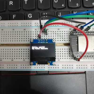
}Setelah upload kode tersebut, ini adalah hasil tampilan di Display OLEDnya:
PWM
Apa si PWM itu? Pulse Width Modulation atau singkatnya PWM merupakan teknik mendapatkan hasil analog. Jadi pada eksperimen kali ini kita akan melakukan uji coba mengatur tingkat kecerahan LED dengan teknik PWM tersebut. Rujukan dari eksperimen kedua ini bersumber pada link
Persiapan
Komponen yang digunakan dalam eksperimen ini adalah:
- Board ESP32
- Lampu LED 1 buah
- Resistor 200 Ohm 1 buah
- Kabel jamper
- Breadboard
Rangkaian
Berikut rangkaian yang digunakan
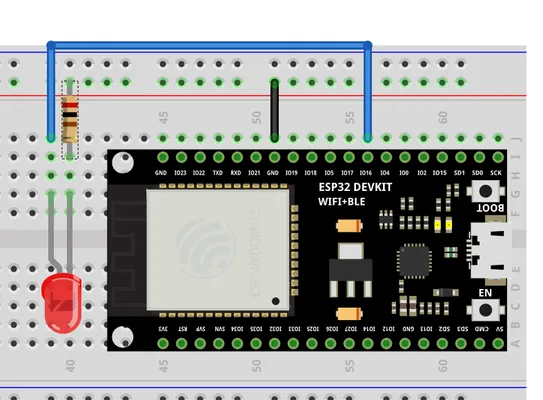
Hubungkan kaki positif LED (anoda/lebih panjang) ke GPIO 16 melalui resistor, dan kaki negatif (katoda/lebih pendek) ke GND.
Code
Berikut kode yang digunakan
// Menentukan PIN LED
const int ledPin = 16;  // GPIO 16

// Pengaturan properti PWM
const int freq = 5000;     // Frekuensi 5000 Hz
const int resolution = 8;  // Resolusi 8-bit (0-255)

void setup() {
  // Mengonfigurasi LED PWM pada GPIO tertentu
  ledcAttachChannel(ledPin, freq, resolution, 0);
}

void loop() {
  // Menambah kecerahan secara bertahap
  for(int dutyCycle = 0; dutyCycle <= 255; dutyCycle++){
    ledcWrite(ledPin, dutyCycle);
    delay(15);
  }

  // Mengurangi kecerahan secara bertahap
  for(int dutyCycle = 255; dutyCycle >= 0; dutyCycle--){
    ledcWrite(ledPin, dutyCycle);
    delay(15);
  }
}- freq = 5000, artinya sinyal akan berkedip sebanyak 5000 kali per detik (5 kHz). Ini sangat cepat sehingga terlihat cahaya yang stabil.
- ledAttachChannel, merupakan fungsi yang krusial bertugas untuk menikahkan pin 16 dengan parameter frekuensi dan resolusi yang dibuat, angka 0 adalah nomor channel PWM yang digunakan (ESP32 punya 16 channel)
- pada fungsi loop, variabel dutyCycle naik dari 0 ke 255, nah setiap kenaikan fungsi ledcWrite akan mengirimkan perintah ke lampu LED untuk sedikit lebih terang lalu menunggu 15 milidetik, loop berikutnya kebalikannya variabel akan turun dari 255 ke 0, sehingga LED perlahan meredup sampai mati.
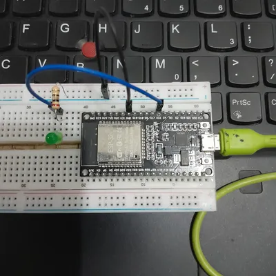
Silahkan upload code tersebut, maka lampu LED terlihat meredup lalu terang secara halus dan berulang. Berikut video hasil eksperimen:
Video Hasil menyalakan lampu LED dengan teknik PWM
Oke sampai sini dulu aja ya laporannya, terimakasih sudah mampir kesini!